3040-00-752-2365

Shouldered Shaft email this page

Images

Reference images of this national stock number
Reference of NSN 3040-00-752-2365 Reference of NSN 3040-00-752-2365

Model or part number: 7522365

Pricing & Availability

Submit this form for current pricing and availability of this NSN.
Part / NSN:
Qty:
Your Email:
Phone:
Ref. / PO #:
Company:
Your Name:

We do not share or sell your information to anyone.
Privacy | Terms

All major credit cards accepted as well as gov. p-cards

About this product
Internal thread on second end is 1/4-28nf-3;

Description

Stop-receiver Fixture Plunger NSN 3040-00-752-2365.

pdf NSN 3040-00-752-2365 Datasheet

MRC:
The style designation indicating the configuration that most nearly corresponds to the appearance of the first end.AAGZ
First End Style:
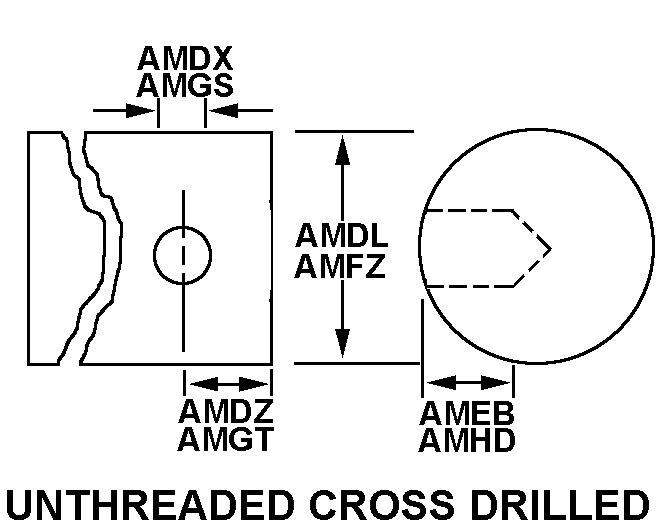
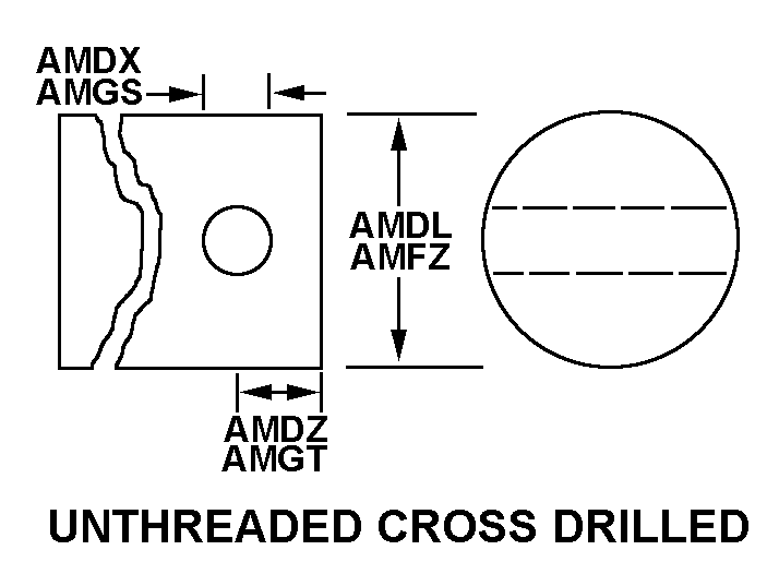
Unthreaded cross drilled
MRC:
A term used to identify the ends as identical or not identical.AAHN
End Similarity:
Not identical
MRC:
The style designation indicating the configuration that most nearly corresponds to the appearance of the second end.AAHP
Second End Style:
Square (round corners)
MRC:
The dimension measured along the longitudinal axis with terminated points at the extreme ends of the item.ABHP
Overall Length:
5.250 inches
MRC:
None.ACMD
Second End Width Across Flats:
Between 0.435 inches and 0.437 inches
MRC:
The length of a straight line which passes through the center of the first end,and terminates at the circumference.AMDL
First End Diameter:
Between 0.6220 inches and 0.6240 inches
MRC:
The length of a straight line which passes through the center of a hole or body of the first end,and terminates at the circumference.AMDX
First End Hole Diameter:
Between 0.3120 inches and 0.3140 inches
MRC:
None.AMDZ
First End Distance From Hole Center To End:
Between 0.458 inches and 0.478 inches
MRC:
A measurement between specified points of the hole at the first end,in distinction from height.AMEB
First End Hole Depth:
Between 0.622 inches and 0.624 inches
MRC:
The length of a straight line which passes through the center of the second end,and terminates at the circumference.AMFZ
Second End Diameter:
Between 0.6692 inches and 0.6695 inches
MRC:
The number of steps provided.ATPC
Step Quantity:
6
MRC:
The length of a straight line which passes through the center of the largest step,and terminates at the circumference.CSPY
Largest Step Diameter:
0.8125 inches
MRC:
None.CTBM
Second End Step Length:
Between 0.875 inches and 0.937 inches
MRC:
The chemical compound or mechanical mixture properties of which the item is fabricated.MATT
Material:
Steel comp 1020 or steel comp 1030
MRC:
The specification,standard,or manufacturers reference,and the classification designation,such as class,condition,temper,and the like,that identifies the material.MDCL
Material Specification:
Qq-s-633 federal specification all material responses
MRC:
--
NIIN:
007522365
MRC:
--
NATO Stock Number:
3040-00-752-2365
MRC:
--
Shelf Life:
N/A
MRC:
--
UOM:
--
MRC:
--
DEMIL:
No
FIIG:
--
FIIG:
A23200
MRC:
--
INC:
22914
MRC:
--
IMM:
AX
Certified products icon

All Products Certified

Factory New, New Material, New Surplus, Overhauled, Serviceable, Repairable, and AS Removed / Used material will be accompanied by a Certificate of Conformance, and any other documents/trace when applicable. We have a 7 year record retention.

Quality inspections icon

Quality | ISO 9001:2015 + AS9120B

We are committed to quality and follow an AS9120 quality management system. AeroBase Group is HAZMAT certified and registered with DDTC, ITAR, and Aviation Suppliers Association (ASA). All products are 100% inspected.

Quality Commitment »

Shipping icon

Shipping

Delivery of IN-STOCK orders ship same-day when order is placed before 2:00 PM EST.

Delivery dates for NON-STOCK items are estimates based on current backlog and are subject to confirmation at the time of order.

Formal Definition

Government issue definition of NSN 3040-00-752-2365

A shaft having two or more different diameters (greater than 0.031 inches (0.79 millimeter)) along its length. It must have one or more of the following conditions: a specified surface finish designation in the range 1 to 125 microinches (0.025 to 3.2 micrometers) arithmetical average (aa), machined peripheral flat(s), circular groove(s), keyway(s), splines, threads, or holes. The ends and/or shoulders may be machined to accommodate bearings, couplings, and the like. It is not designed for use in aligning by fitting into corresponding holes of another item. For items used to support rotating members see axle(1), shouldered. For items not having any of the above conditions see pin, shoulder, headless. Excludes shaft(1), straight; and axle(1), straight.

Import / Export

Schedule B Classification
Schedule B Number
NAIC National Association of Insurance Commissioners
End Use A classification system for U.S. exported and imported merchandise based on principal use rather than the physical characteristics of the merchandise. End-Use codes are assigned by the Bureau of Economic Analysis under the U.S. Department of Commerce.
SITC Commodity classification system defined by the United Nations.
USDA
HITECH
Schedule B:
8483105000
NAICS:
333613
End Use Class:
21180
SITC:
74810
USDA:
1
HITECH:
0

Schedule B Codes Definitions:

Schedule B 8483105000

Transmission Shafts and Cranks, Except Camshafts and Crankshafts

End Use Code 21180

Industrial Machines, Other

Standard Intl. Trade Class (SITC) 74810

Transmission Shafts (including Cam and Crank Shafts) and Cranks

Manufacturers

This NSN is registered to the following cage codes.
Compare Now »
Clear | Hide