
5985-01-399-0614

Variable Attenuator email this page
ITAR Registered

Images

Reference images of this national stock number
Reference of NSN 5985-01-399-0614 Reference of NSN 5985-01-399-0614 Reference of NSN 5985-01-399-0614 Reference of NSN 5985-01-399-0614 Reference of NSN 5985-01-399-0614 Reference of NSN 5985-01-399-0614 Reference of NSN 5985-01-399-0614 Reference of NSN 5985-01-399-0614 Reference of NSN 5985-01-399-0614 Reference of NSN 5985-01-399-0614 Reference of NSN 5985-01-399-0614 Reference of NSN 5985-01-399-0614 Reference of NSN 5985-01-399-0614 Reference of NSN 5985-01-399-0614 Reference of NSN 5985-01-399-0614 Reference of NSN 5985-01-399-0614 Reference of NSN 5985-01-399-0614

Model or part number: 1211522-201

Pricing & Availability

Submit this form for current pricing and availability of this NSN.
Part / NSN:
Qty:
Your Email:
Phone:
Ref. / PO #:
Company:
Your Name:

We do not share or sell your information to anyone.
Privacy | Terms

All major credit cards accepted as well as gov. p-cards
Description

Toggle Attenuator NSN 5985-01-399-0614.

pdf NSN 5985-01-399-0614 Datasheet

MRC:
The primary application for which the item is designed.AAFS
Application Design:
Transmission line
MRC:
The style designation indicating the configuration that most nearly corresponds to the appearance of the body.AAQL
Body Style:
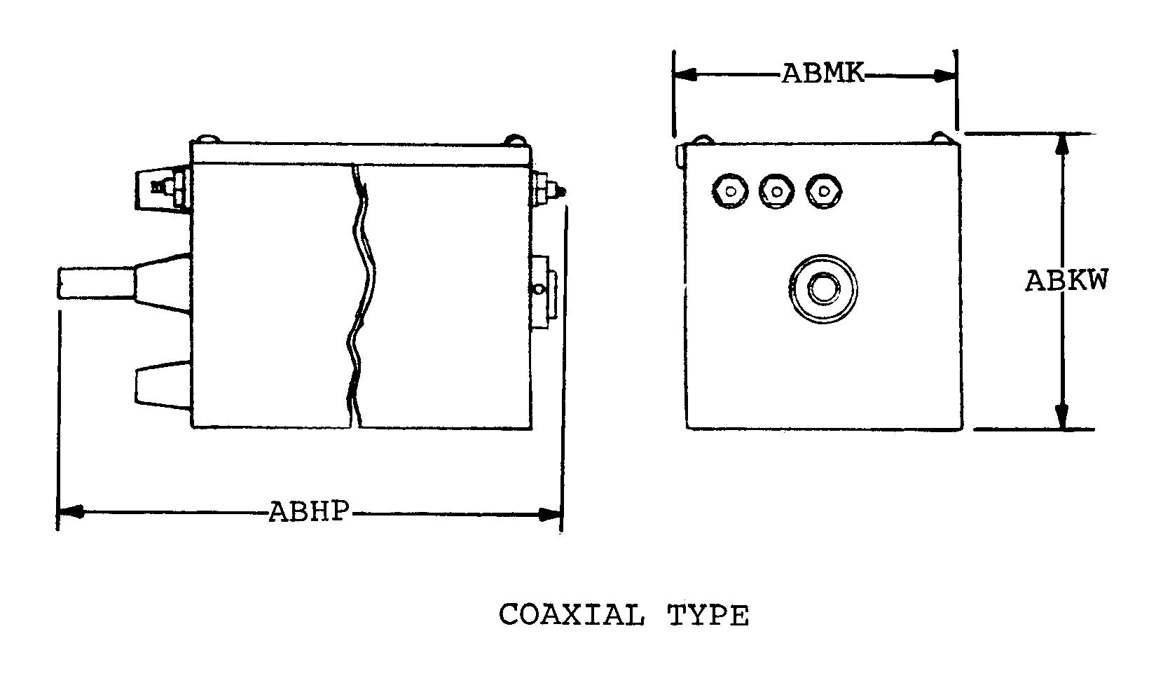
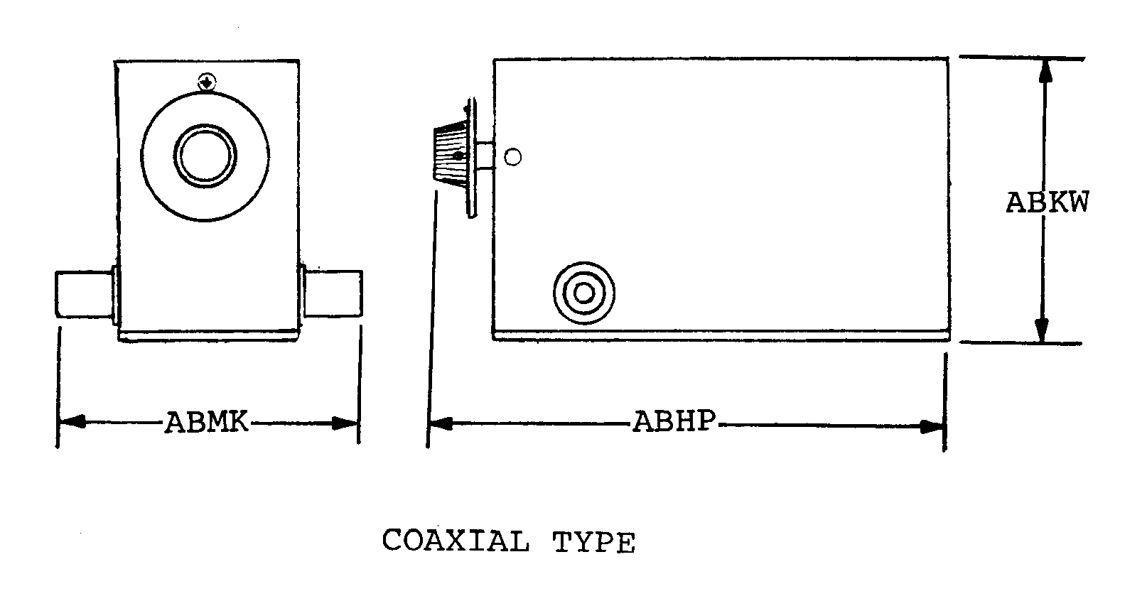
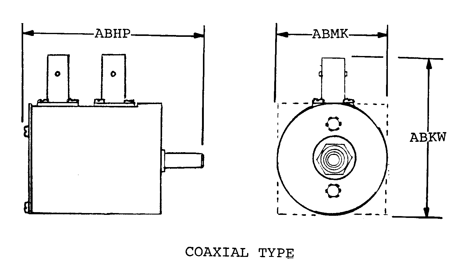
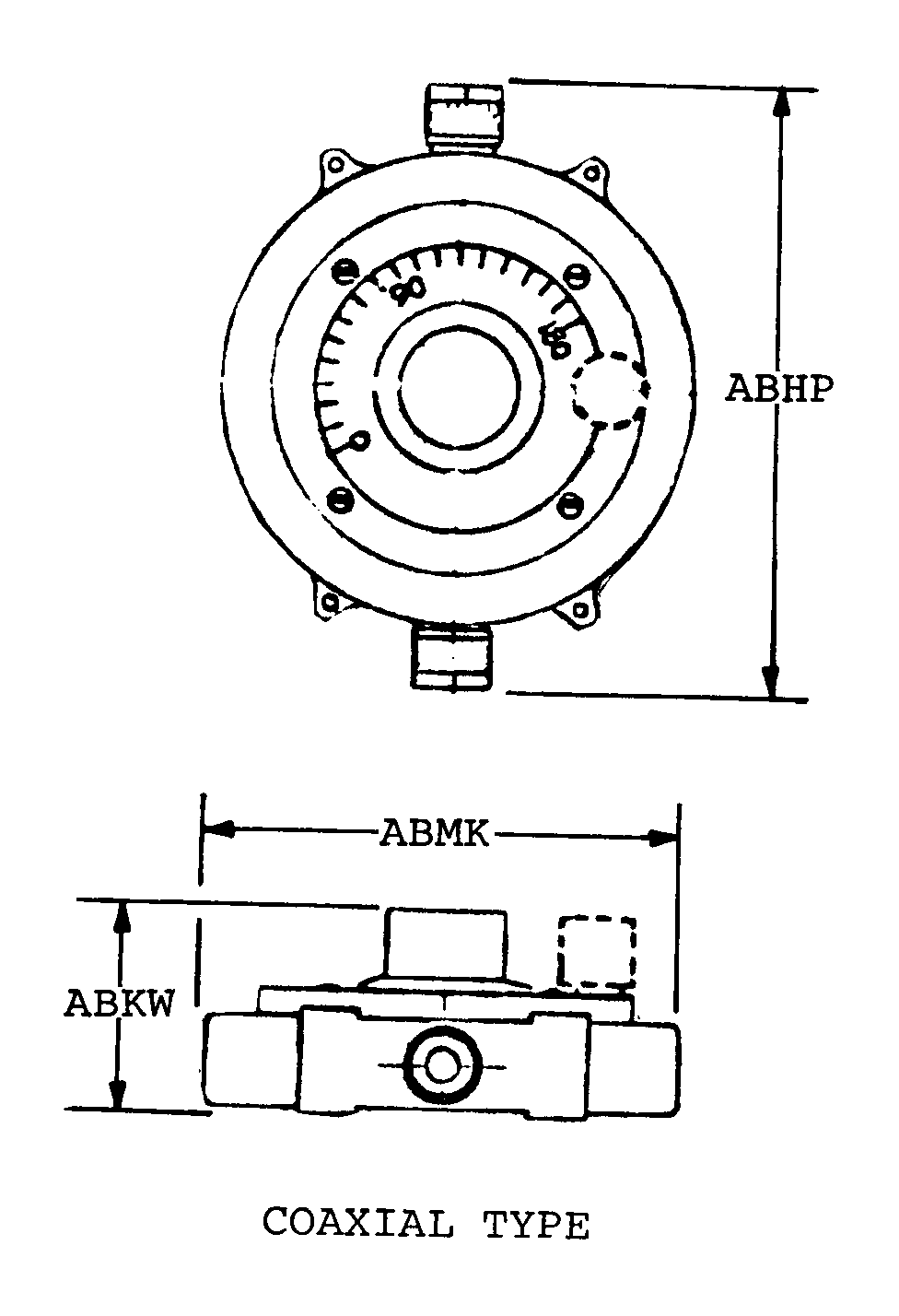
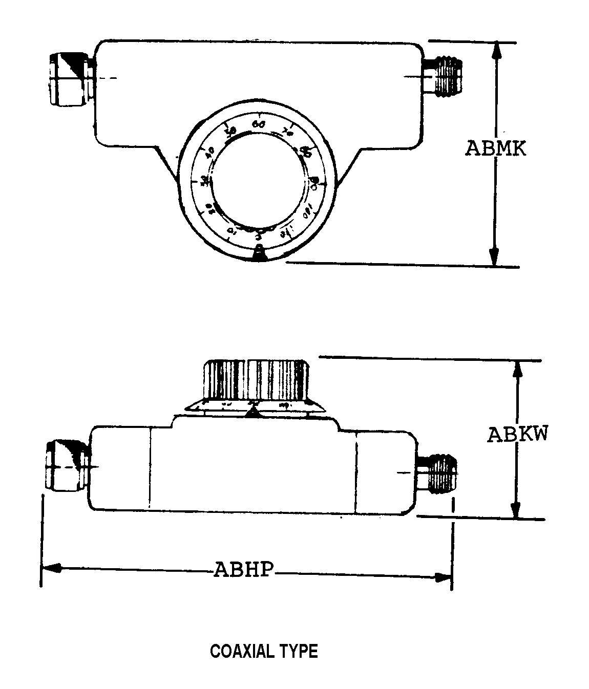
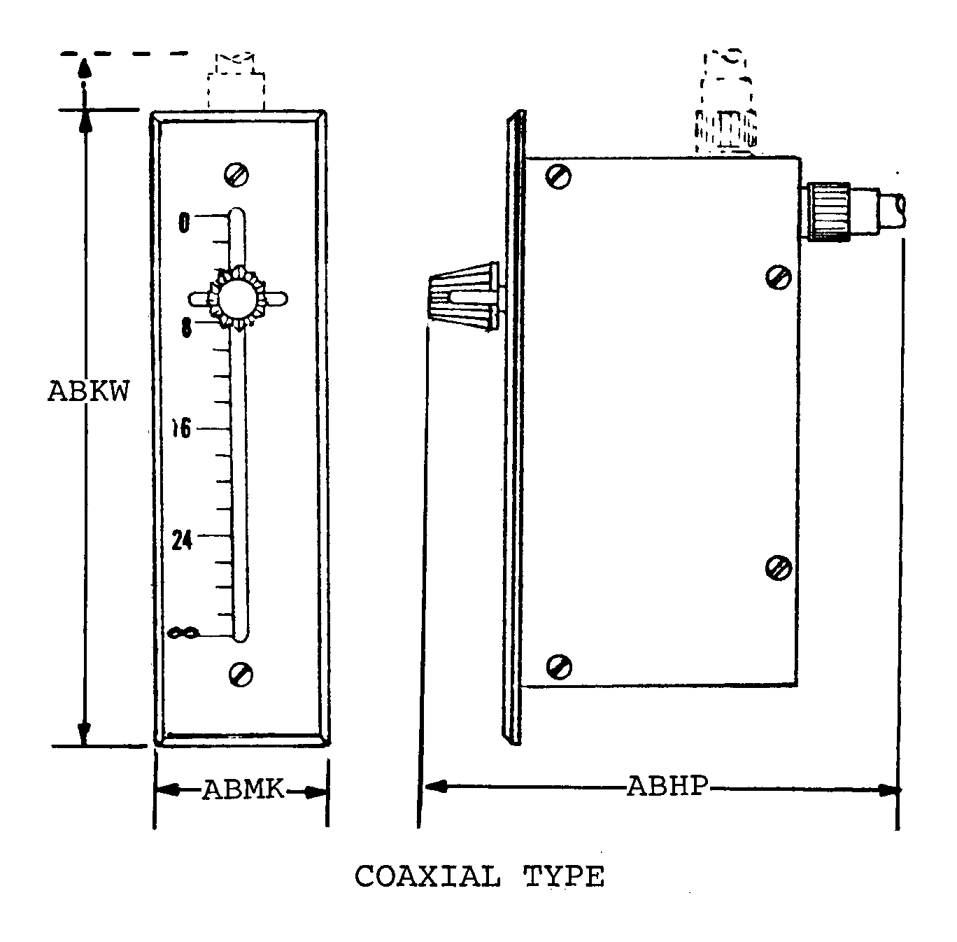
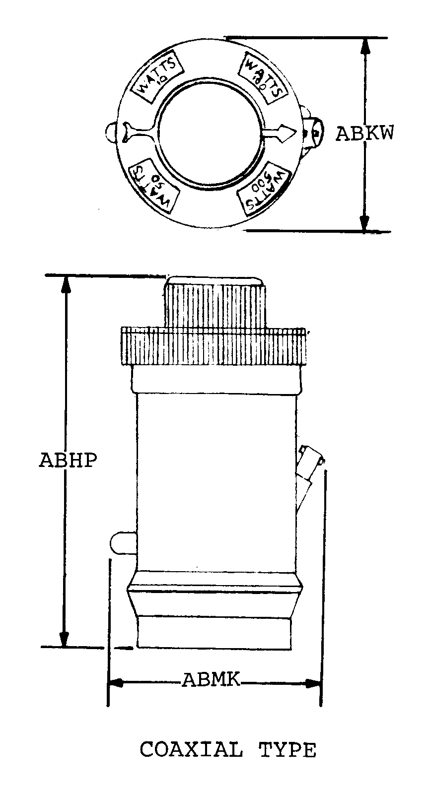
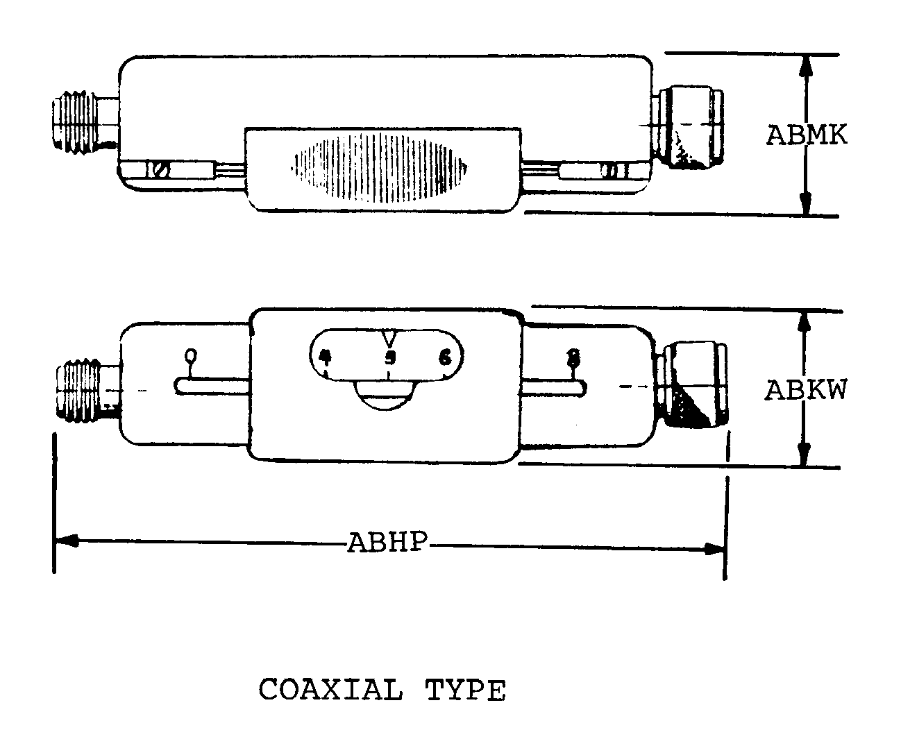
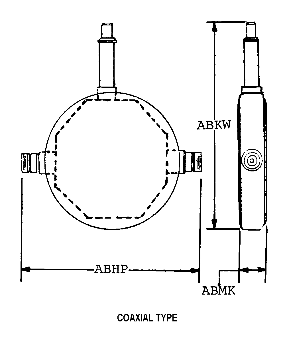
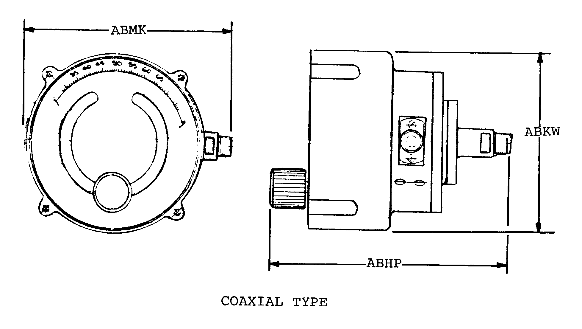
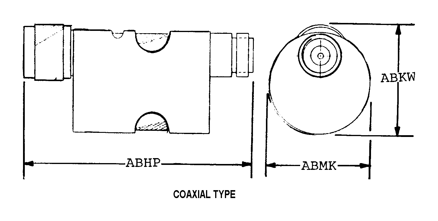
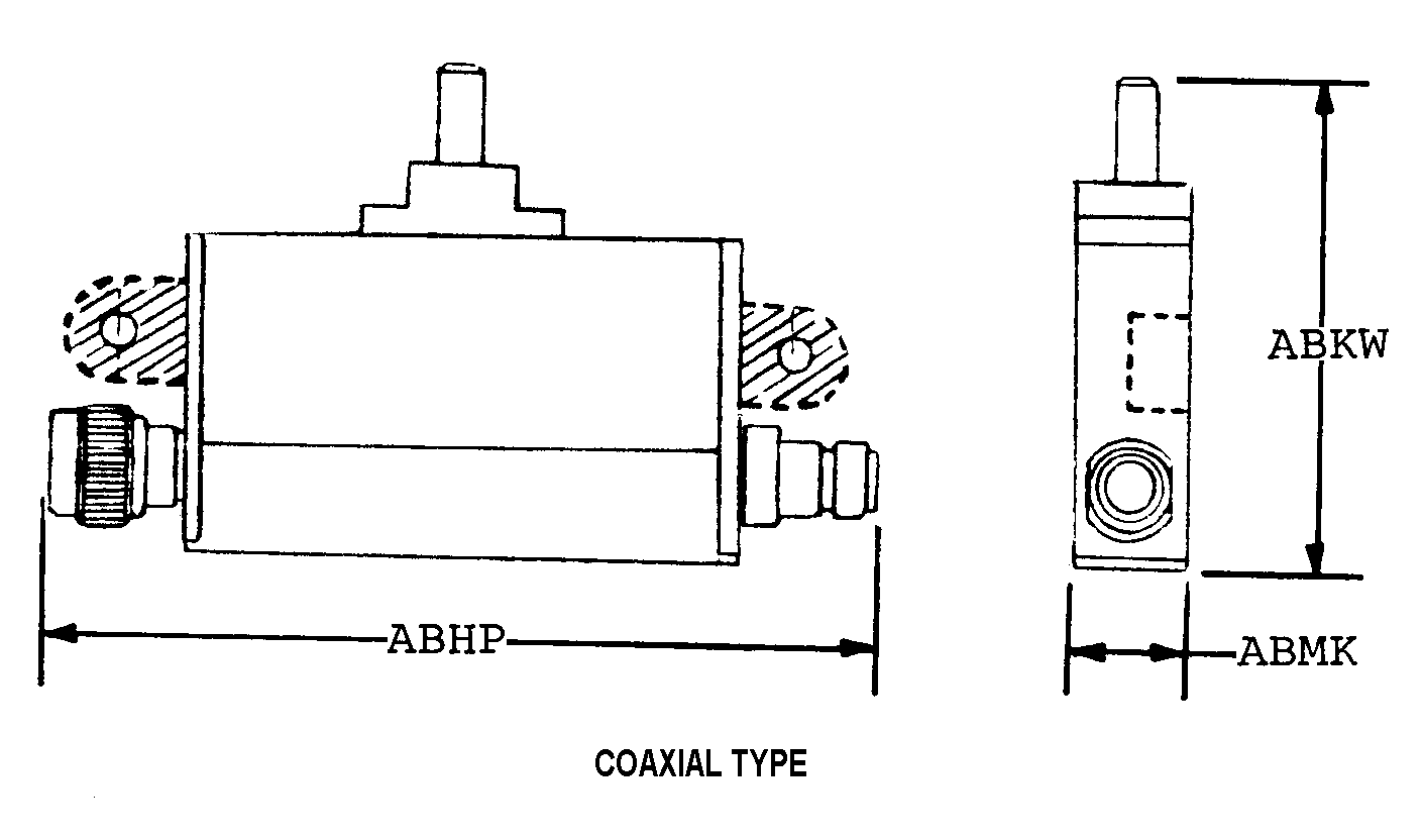
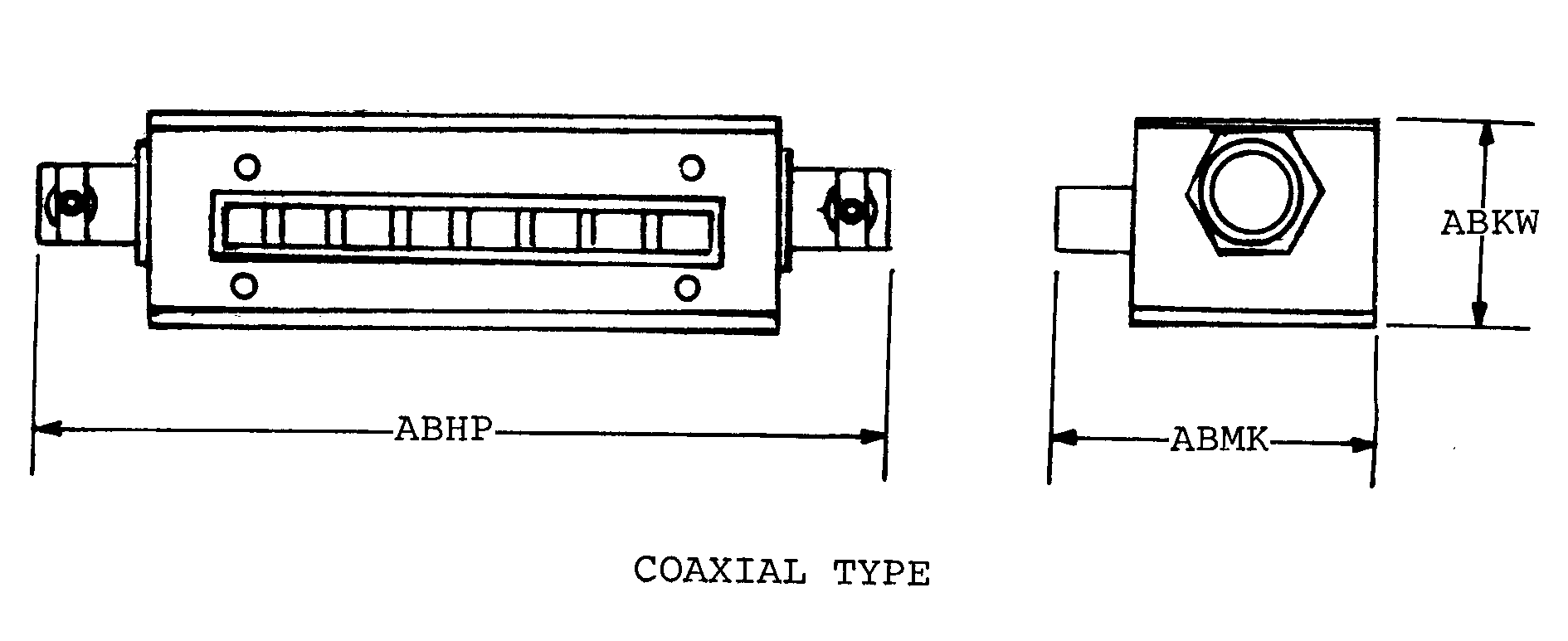
Coaxial type
MRC:
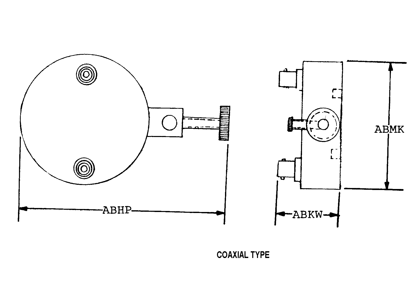
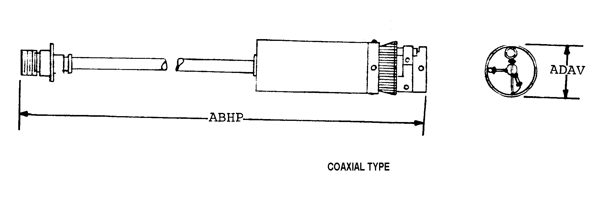
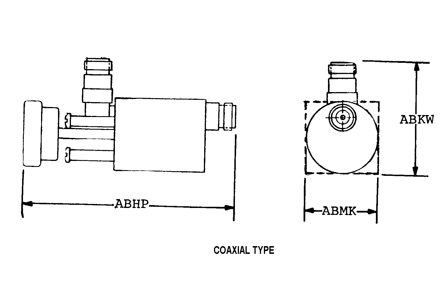
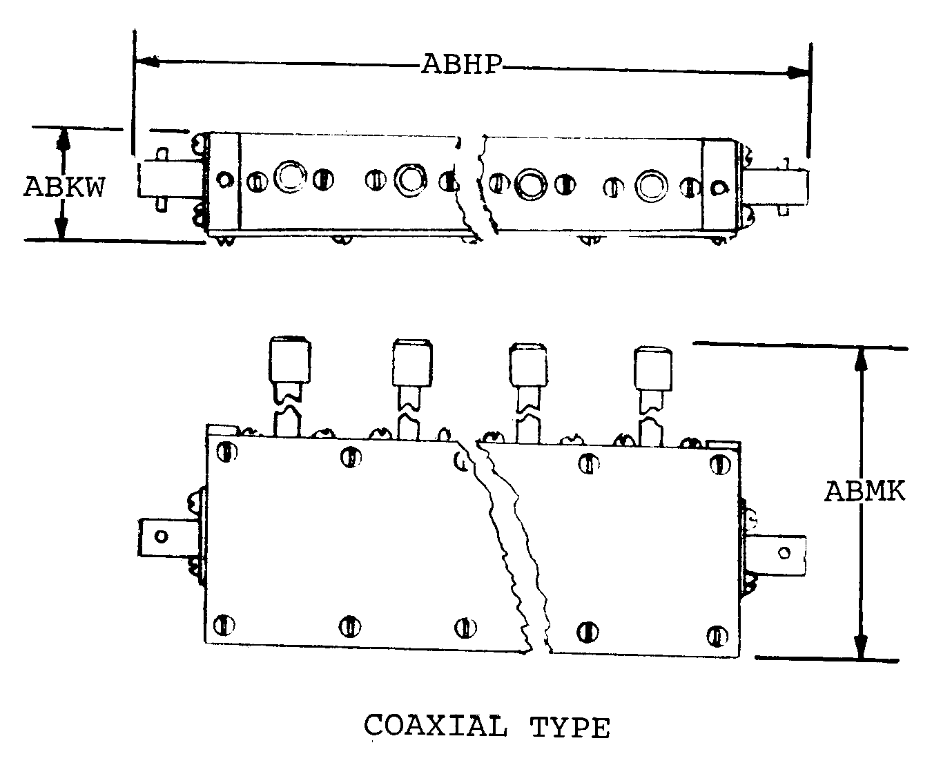
The dimension measured along the longitudinal axis with terminated points at the extreme ends of the item.ABHP
Overall Length:
2.260 inches
MRC:
The distance between the center of one mounting facility and the center of the adjacent mounting facility parallel to the length.ABKQ
Center To Center Distance Between Mounting Facilities Parallel To Length:
1.840 inches
MRC:
The distance between the center of one mounting facility and the center of the adjacent mounting facility parallel to the width.ABKR
Center To Center Distance Between Mounting Facilities Parallel To Width:
2.340 inches
MRC:
The distance measured in a straight line from the bottom to the top of an item.ABKW
Overall Height:
2.870 inches
MRC:
An overall measurement taken at right angles to the length of an item,in distinction from thickness.ABMK
Overall Width:
0.560 inches
MRC:
The ratio of the maximum to the minimum amplitude of pressure /voltage/ measured along the path of the waves.AHTW
Voltage Standing Wave Ratio:
1.40
MRC:
A letter or group of letters used to designate the particular coaxial connector series.AHUC
Coaxial Connector Series Designation:
Sma
MRC:
The amount of electrical energy that can be dissipated.AJDB
Power Rating:
5.0 watts average
MRC:
A designation distinguishing one group of screw thread diameter-pitch combinations from another by the number of threads per measurement scale for a specific diameter on the mounting facility.AKEJ
Mounting Facility Screw Thread Series Designator:
Unc
MRC:
The mathematical relationship of power available at the load before and after addition of the item to the circuit,set to its lowest value of attenuation,expressed in maximum decibels.ASYC
Insertion Loss At Minimum Attenuation In Maximum Decibels:
0.3
MRC:
The overall limits of decrease of the amplitude ratio of a signal between the input and output of the item,expressed in decibels.ASYD
Overall Attenuation Range In Decibels:
+0.0/+3.0
MRC:
The means by which the attenuation can be varied from the minimum to the maximum setting.ASYF
Attenuation Variation Method:
Continuous
MRC:
Indicates the type and number of facilities by which the item is mounted.AXHR
Mounting Facility Type And Quantity:
4 threaded hole
MRC:
The minimum and maximum cyclic changes,per unit of time,for which an item is rated.BNGR
Frequency Range:
Between 2.700 gigahertz and 2.900 gigahertz
MRC:
The overall limits of permissible variation in the attenuation accuracy from the nominal value at a specified frequency rating or range,expressed in decibels.BQNR
Overall Attenuation Accuracy In Decibels:
-0.30/+0.30
MRC:
The number of mounting threads on the item measured on a line parallel to the thread axis,including incomplete threads.CGGK
Mounting Thread Quantity:
40 per inch
MRC:
Indicates the type and number of facilities for adjusting the item.CQTQ
Adjustment Device Type And Quantity:
1 slotted screw
MRC:
The general configuration and relative position of the facilities provided for mounting the item.CQYJ
Mounting Facility Pattern:
Four position rectangular
MRC:
The nominal length of a straight line which passes through the center of a coaxial cylinder which would bound the crest of an external thread or the root of an internal thread.CRYY
Mounting Facility Screw Thread Diameter:
0.112 inches
MRC:
The total opposition (resistive and reactive) to the flow of alternating current,expressed in ohms.CTGG
Impedance Rating In Ohms:
50.0 input-output
MRC:
Indicates the type and number of terminals for providing electrical connection.TTQY
Terminal Type And Quantity:
2 connector, coaxial, female
MRC:
--
NIIN:
013990614
MRC:
--
NATO Stock Number:
5985-01-399-0614
MRC:
--
Shelf Life:
N/A
MRC:
--
UOM:
--
MRC:
--
DEMIL:
FIIG:
--
FIIG:
A223A0
MRC:
--
INC:
00838
MRC:
--
IMM:
TX
Certified products icon

All Products Certified

Factory New, New Material, New Surplus, Overhauled, Serviceable, Repairable, and AS Removed / Used material will be accompanied by a Certificate of Conformance, and any other documents/trace when applicable. We have a 7 year record retention.

Quality inspections icon

Quality | ISO 9001:2015 + AS9120B

We are committed to quality and follow an AS9120 quality management system. AeroBase Group is HAZMAT certified and registered with DDTC, ITAR, and Aviation Suppliers Association (ASA). All products are 100% inspected.

Quality Commitment »

Shipping icon

Shipping

Delivery of IN-STOCK orders ship same-day when order is placed before 2:00 PM EST.

Delivery dates for NON-STOCK items are estimates based on current backlog and are subject to confirmation at the time of order.

Formal Definition

Government issue definition of NSN 5985-01-399-0614

A device for reducing the strength of an alternating current signal either continuously or in steps, without causing appreciable signal distortion, by maintaining substantially constant output and/or input impedance match. Continuously variable resistive devices must consist of at least two sections or one section with at least two rotating contacts. The item must have an overall attenuation rating. Includes tandem mounted variable resistors designed to function as an attenuator but whose terminals are not connected. See also resistor, vaiable (as modified).

Packaging & Dimensions

MIL-STD codes: http://www.dla.mil/LandandMaritime/.../MILSTD2073Codes.aspx
Est. Pack Size
Est. Pack Weight
Est. Item Weight
Est. Item Dim.
Pack Size:
--
Paclk Weight:
--
Item Weight:
--
Item Dim:
--
Container
OPI
SPI No.
SPI Rev.
SPC Mkg.
LVL A
LVL B
LVL C
Container:
--
OPI:
O
SPI No.:
SPI Rev.:
SPC Mkg:
00
LVL_A:
Q
LVL_B:
Q
LVL_C:
CUSH
MOP
CATEG.
PRES MAT
WRAP MAT
ICQ
THK
TOS
UCL
CUSH DUN:
XX
MOP:
31
PKG:
69F0
PRES MAT:
00
WRAP MAT:
00
ICQ:
AAA
THK:
X
TOS:
UCL:

Packaging Codes Definitions:

LVL A Code (LVL_A) Q

Packing shall be accomplished in accordance with table c.Ii for the packing level specified. closure, sealing and reinforcement shall be in accordance with applicable specification for shipping container.

LVL B Code (LVL_B) Q

Packing shall be accomplished in accordance with table c.Ii for the packing level specified. closure, sealing and reinforcement shall be in accordance with the appropriate shipping container specification.

Procedure Indicator Code (OPI) O

Options can be exercised as to specific method of preservation or dod approved packaging materials to be used. however, basic preservation method shall be retained, supplemental data shall be complied with, and unit package dimensions shall not be increased by more than one inch. equal or better protection shall be given the item and there shall be no increase in the package cost.

Special Markings Code (SPC_MKG) 00

No special marking.

Method of Preservation (MOP) 31

Waterproof bag, sealed.

Preservation Material (PRES_MAT) 00

No requirement.

Import / Export

Schedule B Classification
Schedule B Number
NAIC National Association of Insurance Commissioners
End Use A classification system for U.S. exported and imported merchandise based on principal use rather than the physical characteristics of the merchandise. End-Use codes are assigned by the Bureau of Economic Analysis under the U.S. Department of Commerce.
SITC Commodity classification system defined by the United Nations.
USDA
HITECH
Schedule B:
8529109000
NAICS:
334220
End Use Class:
21400
SITC:
76493
USDA:
1
HITECH:
0

Schedule B Codes Definitions:

Schedule B 8529109000

Antenna & Antenna Reflectors Of All Kinds; Parts Suitable For Use Soley Or Principally W/ Apparatus Of Heading 8525 To 8528, Nesoi

End Use Code 21400

Telecommunications Equipment

Standard Intl. Trade Class (SITC) 76493

Parts Of Television Receivers, Radiobroadcast Receivers, Transmission Apparatus For Radio Telephony, Telegraphy, Broadcasting Or Television Etc.

Freight

Universal / National freight and handling information
NMFC
Class
UFC
LTL
LCL
WCC
TCC
SHC
ADC
ACC
NMFC:
061700
NMF Description:
Elec Appliances/instruments Noi
UFC:
34580
LTL:
100.0
LCL:
--
WCC:
658
TCC:
Z
SHC:
9
ADC:
A
ACC:
H

Freight Codes Definitions:

Cargo Type (TCC) Z

No special type of cargo code applicable.

Water Commodity (WCC) 658

Electrical appliances, small.

Air Commodity (ACC) H

Instruments/equipment/supplies for radio, communications, electrical, laboratory, etc. (includes signal corps).

Air Dimensions (ADC) A

Shipment is not a consolidation and does not exceed 84 inches in any dimension.

Air Special Handling (SHC) 9

Other or no special handling required (sh)

Manufacturers

This NSN is registered to the following cage codes.
Compare Now »
Clear | Hide