5925-01-470-0438

Circuit Breaker email this page

Images

Reference images of this national stock number
Reference of NSN 5925-01-470-0438 Reference of NSN 5925-01-470-0438 Reference of NSN 5925-01-470-0438 Reference of NSN 5925-01-470-0438 Reference of NSN 5925-01-470-0438 Reference of NSN 5925-01-470-0438 Reference of NSN 5925-01-470-0438 Reference of NSN 5925-01-470-0438 Reference of NSN 5925-01-470-0438 Reference of NSN 5925-01-470-0438 Reference of NSN 5925-01-470-0438 Reference of NSN 5925-01-470-0438 Reference of NSN 5925-01-470-0438 Reference of NSN 5925-01-470-0438 Reference of NSN 5925-01-470-0438 Reference of NSN 5925-01-470-0438 Reference of NSN 5925-01-470-0438 Reference of NSN 5925-01-470-0438 Reference of NSN 5925-01-470-0438 Reference of NSN 5925-01-470-0438 Reference of NSN 5925-01-470-0438 Reference of NSN 5925-01-470-0438

Model or part number: M55629/1-380

Pricing & Availability

Submit this form for current pricing and availability of this NSN.
Part / NSN:
Qty:
Your Email:
Phone:
Ref. / PO #:
Company:
Your Name:

We do not share or sell your information to anyone.
Privacy | Terms

All major credit cards accepted as well as gov. p-cards
Description

Overload Switch NSN 5925-01-470-0438.

pdf NSN 5925-01-470-0438 Datasheet

MRC:
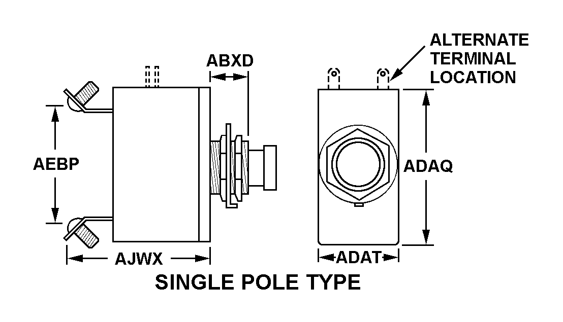
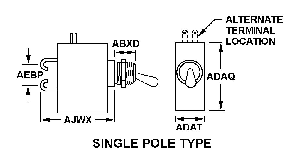
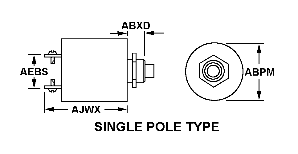
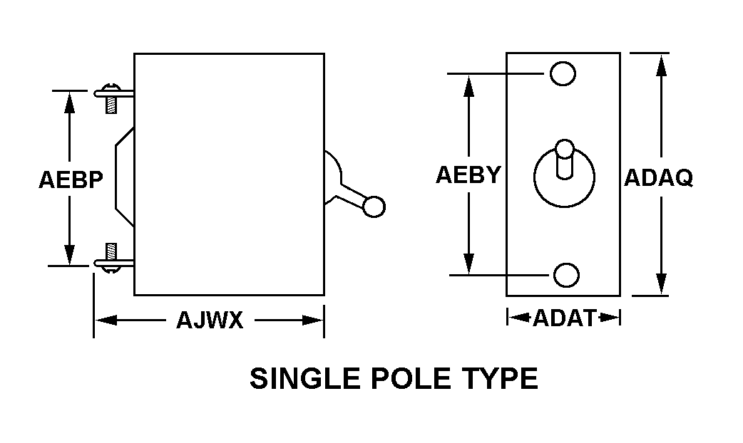
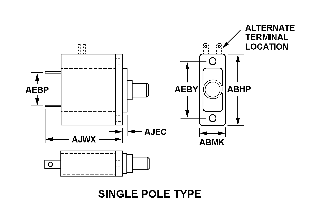
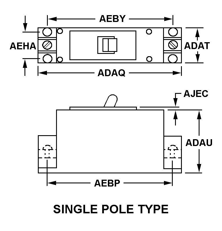
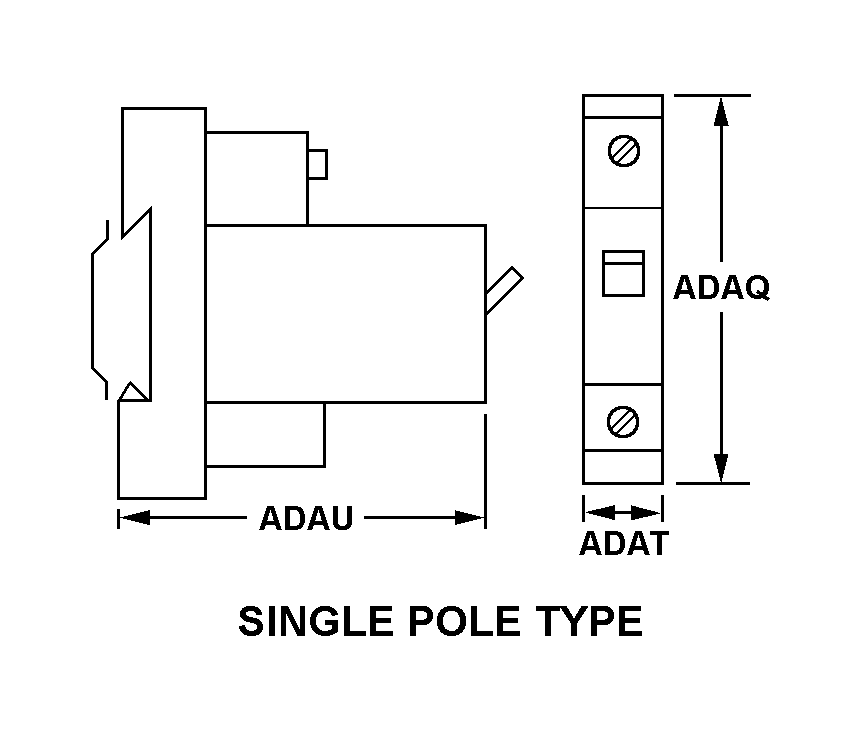
The style designation indicating the configuration that most nearly corresponds to the appearance of the body.AAQL
Body Style:
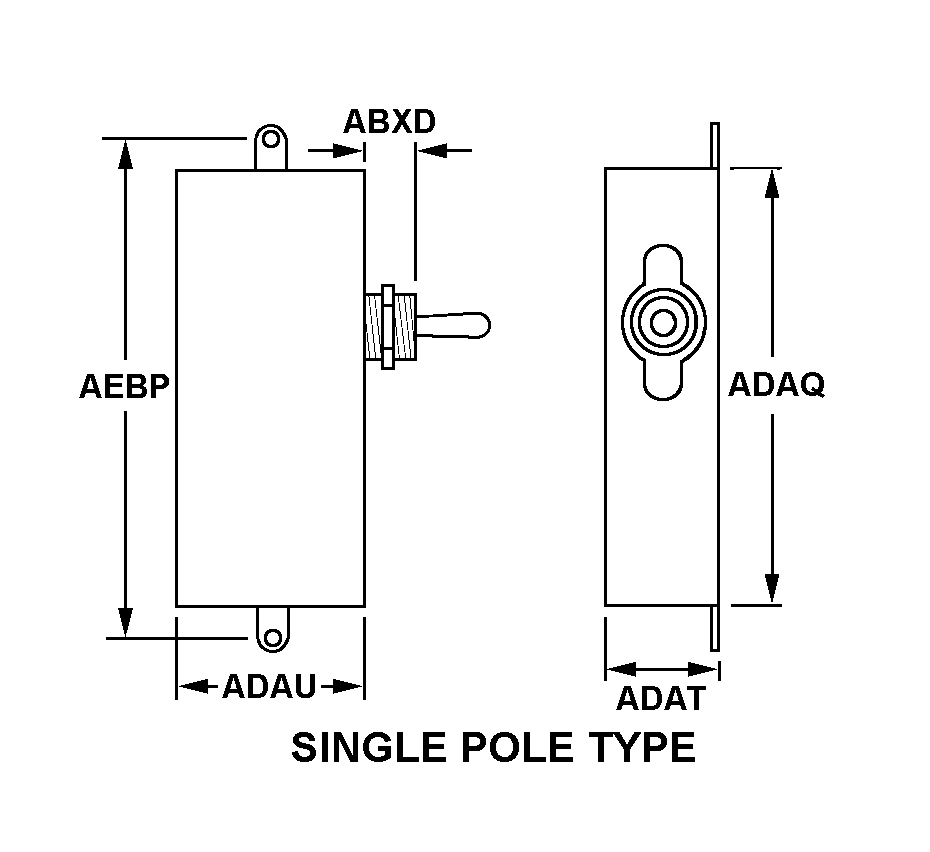
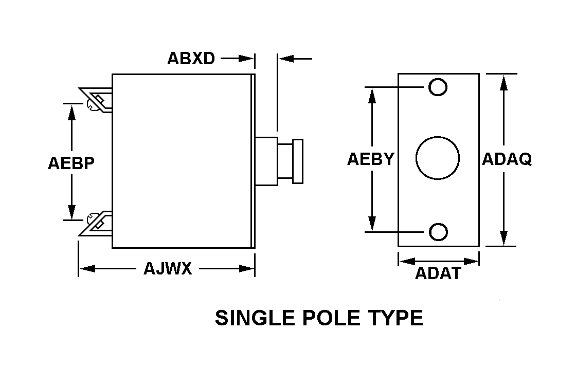
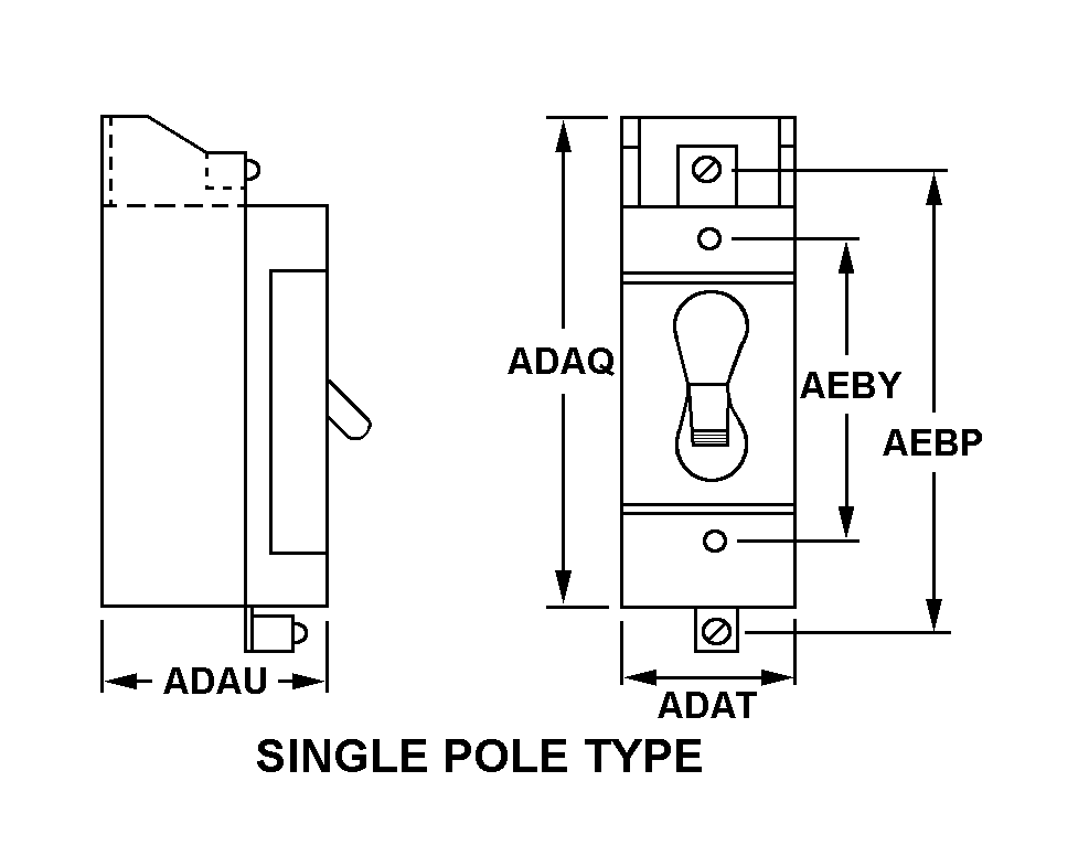
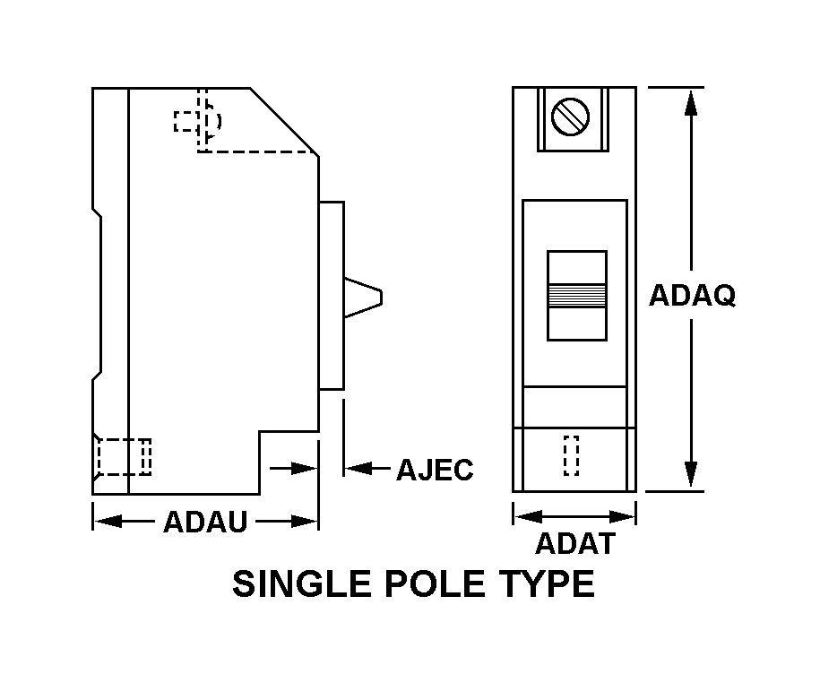
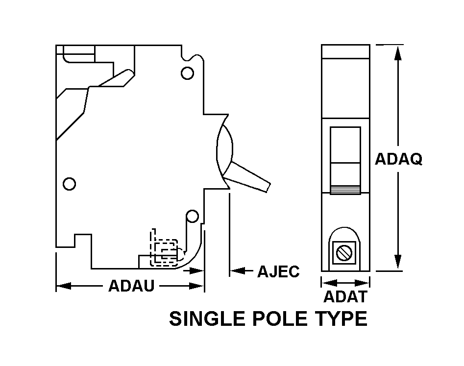
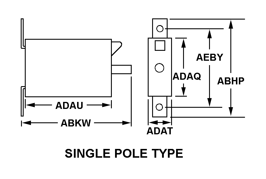
Single pole type
MRC:
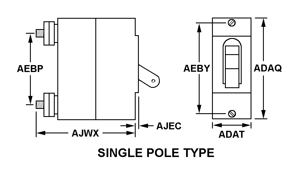
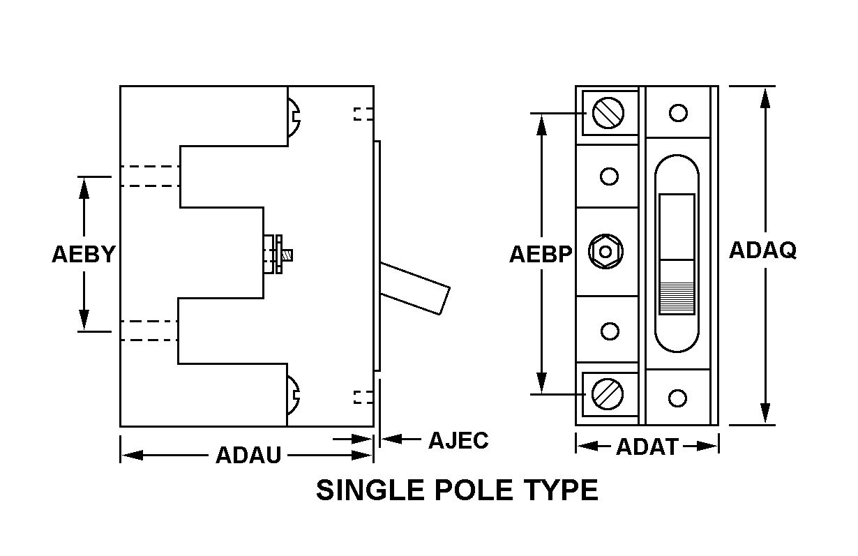
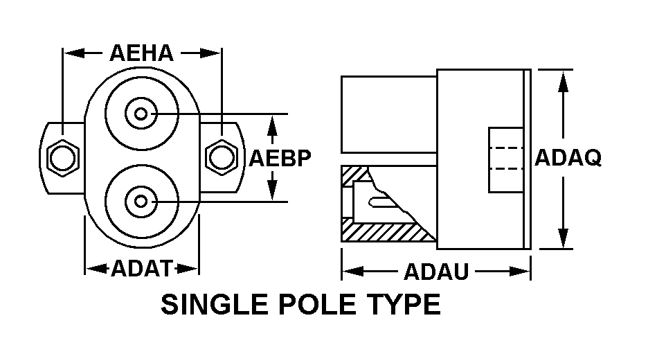
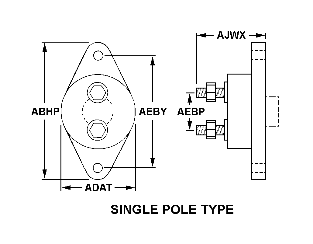
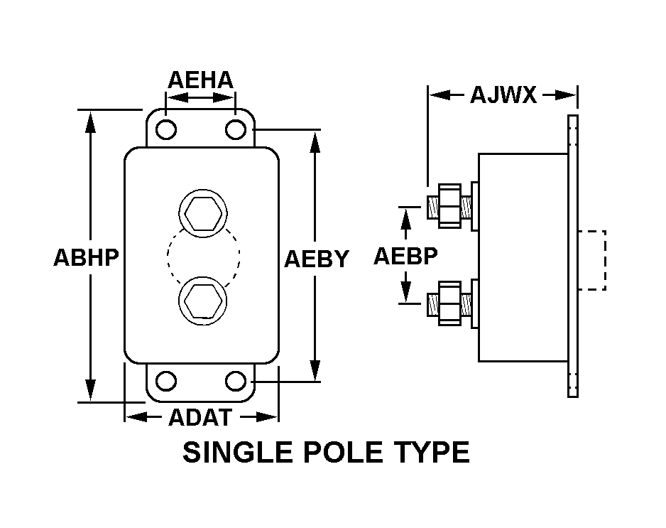
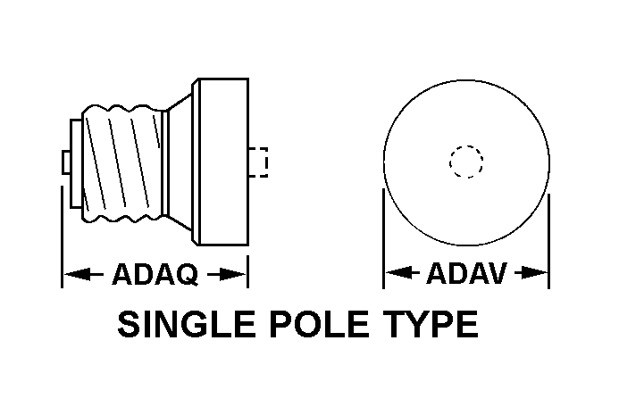
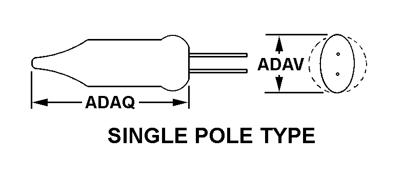
A measurement of the longest dimension of the body,in distinction from width.ADAQ
Body Length:
2.530 inches
MRC:
A measurement taken at right angles to the length of the body,in distinction from thickness.ADAT
Body Width:
Between 0.730 inches and 0.780 inches
MRC:
The element,compound,or mixture of which the case is fabricated,excluding any surface treatment.ADTV
Case Material:
Plastic
MRC:
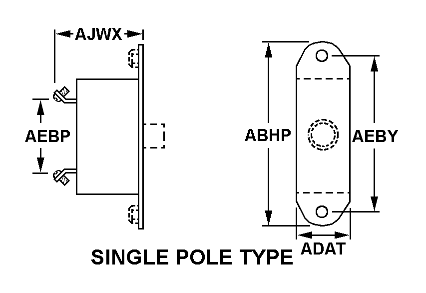
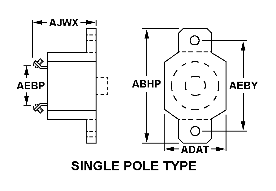
The center to center distance between terminals parallel to the length of the item.AEBP
Center To Center Distance Between Terminals Parallel To Length:
Between 1.660 inches and 1.960 inches
MRC:
The distance between centerlines of mounting facilities parallel to the length of the item.AEBY
Distance Between Centerlines Of Mounting Facilities Parallel To Body Length:
Between 2.046 inches and 2.078 inches
MRC:
The national stock number or the identification information of the end equipment for which the item is a part.AGAV
End Application:
5805-01-452-5730
MRC:
None.AJEC
Boss Height:
Between 0.109 inches and 0.171 inches
MRC:
None.AJWX
Mounting Surface To Terminal End Distance:
2.553 inches
MRC:
The number of poles included in the item.AKPX
Pole Quantity:
1
MRC:
Indicates the type and number of facilities by which the item is mounted.AXHR
Mounting Facility Type And Quantity:
2 threaded hole
MRC:
The maximum current load that each pole is rated to carry continuously.CPLM
Maximum Continuous Load Current Rating Per Pole:
15.0 amperes dc single location
MRC:
Indicates the type and value of operating voltage for which each pole is designed to operate,expressed in volts.CPRF
Operating Voltage Type And Rating Per Pole In Volts:
50.0 dc single location
MRC:
Indicates the type and value of the maximum short circuit current that the item will successfully interrupt,per pole,at the specified rated voltage,expressed in amperes.CPRG
Maximum Interrupting Capacity Current Type And Rating Per Pole In Amps:
1000.0 dc single location
MRC:
Indicates the type of electrical condition that will cause the device to trip.CPRH
Circuit Protection Type:
Overvoltage single location
MRC:
The means by which the trip mechanism is released.CPRJ
Trip Release Method:
Magnetic single location
MRC:
Denotes the type of trip release action.CPRL
Trip Release Characteristic:
Time delay single location
MRC:
The continuous current rating per pole at which the device must trip in a specified time,expressed in percent.CPRN
Ultimate Trip Rating Of Continuous Current Rating Per Pole In Percent:
125.0 single location
MRC:
The means provided to reposition the mechanism so that the device is ready to function.CPRQ
Reset Method:
Manual
MRC:
Indicates the type of mechanism provided for tripping main contacts.CPRR
Main Contact Tripping Mechanism Type:
Trip free
MRC:
The basic internal electrical configuration of the trip mechanism.CPSM
Internal Trip Release Configuration:
Series trip single location
MRC:
A designation that is used for the purpose of general identification of the thread.CQJX
Thread Size:
0.125 inches
MRC:
The length of time,expressed in seconds,that an overload may exist before the device will trip at a specified continuous current.CQWN
Trip Delay Time In Seconds Per Rated Continuous Current:
0.500 at 125 pct single location and 12.000 at 125 pct single location
MRC:
A designation distinguishing one group of thread diameter-pitch combinations from another by the number of threads per measurement scale for a specific diameter.THSD
Thread Series Designator:
Unc
MRC:
Indicates the type and number of terminals for providing electrical connection.TTQY
Terminal Type And Quantity:
2 threaded stud
MRC:
--
NIIN:
014700438
MRC:
--
NATO Stock Number:
5925-01-470-0438
MRC:
--
Shelf Life:
N/A
MRC:
--
UOM:
--
MRC:
--
DEMIL:
No
FIIG:
--
FIIG:
A030A0
MRC:
--
INC:
00136
MRC:
--
IMM:
TX
Certified products icon

All Products Certified

Factory New, New Material, New Surplus, Overhauled, Serviceable, Repairable, and AS Removed / Used material will be accompanied by a Certificate of Conformance, and any other documents/trace when applicable. We have a 7 year record retention.

Quality inspections icon

Quality | ISO 9001:2015 + AS9120B

We are committed to quality and follow an AS9120 quality management system. AeroBase Group is HAZMAT certified and registered with DDTC, ITAR, and Aviation Suppliers Association (ASA). All products are 100% inspected.

Quality Commitment »

Shipping icon

Shipping

Delivery of IN-STOCK orders ship same-day when order is placed before 2:00 PM EST.

Delivery dates for NON-STOCK items are estimates based on current backlog and are subject to confirmation at the time of order.

Parts and Components for Automat Telephone Central Office NSN 5805-01-452-5730 Parts and components for this end application.

NSN Component Description
NSN 5925-01-470-0406 Circuit Breaker
NSN 5925-01-470-0438 Circuit Breaker
NSN 5935-01-470-3960 Electrical Plug Connector
NSN 5935-01-470-4230 Electrical Plug Connector
NSN 5935-01-470-4274 Electrical Receptacle Connector
NSN 5935-01-470-7440 Electrical Connector Backshell
NSN 5935-01-470-7441 Electrical Connector Backshell
NSN 5935-01-470-7442 Electrical Connector Backshell
NSN 5935-01-470-7443 Electrical Connector Backshell
NSN 5935-01-470-7445 Electrical Connector Backshell
NSN 5998-01-470-7707 Electronic Components Assembly
NSN 5998-01-470-7739 Electronic Components Assembly
NSN 5998-01-470-8011 Electronic Components Assembly
NSN 5340-01-470-8386 Dust And Moistu Protective Cover
NSN 5340-01-470-8408 Dust And Moisture Protective Cap
NSN 5340-01-470-8419 Dust And Moistu Protective Cover
NSN 5940-01-470-8459 Terminal Board Cover
NSN 5940-01-470-8469 Terminal Board Cover
NSN 5940-01-470-8474 Terminal Board Cover
NSN 5940-01-470-8478 Terminal Board Cover
NSN 5940-01-470-8762 Terminal Board Cover
NSN 5940-01-470-8763 Terminal Board Cover
NSN 5940-01-470-8768 Terminal Board Cover
NSN 5940-01-470-8817 Terminal Board Cover
NSN 5940-01-470-8820 Terminal Board Cover
NSN 5935-01-470-8822 Electrical Receptacle Connector
NSN 5935-01-470-8824 Electrical Plug Connector
NSN 5920-01-470-8851 Electrical Surge Arrester
NSN 5340-01-470-9046 Mounting Plate
NSN 5940-01-470-9115 Terminal Board Cover
NSN 6145-01-470-9503 Electrical Special Purpose Cable
NSN 5935-01-470-9548 Electrical Connector Backshell
NSN 5935-01-470-9576 Electrical Receptacle Connector
NSN 5307-01-470-9643 Self-locking Stud
NSN 5340-01-470-9823 Synchro Clamp

Formal Definition

Government issue definition of NSN 5925-01-470-0438

A device with means other than fuses for automatically opening the circuit in which it is installed when the current varies from the predetermined value for which the device is set. May include provisions for manual operation. At least one set of contacts must be in series with the actuating element(s). A combination of semiconductor and passive devices may be used in lieu of contacts. For automatically operated items in which the actuating (tripping) element and contacts are not in series, see relay (as modified). For items which are operated both manually and automatically but the actuating elements and contact are not in series, see relay-switch. Excludes circuit breaker box and magneto "breaker" assemblies. See also switch (as modified); and controller.

Packaging & Dimensions

MIL-STD codes: http://www.dla.mil/LandandMaritime/.../MILSTD2073Codes.aspx
Est. Pack Size
Est. Pack Weight
Est. Item Weight
Est. Item Dim.
Pack Size:
4.0 X 4.0 X 1.0
Paclk Weight:
--
Item Weight:
--
Item Dim:
--
Container
OPI
SPI No.
SPI Rev.
SPC Mkg.
LVL A
LVL B
LVL C
Container:
--
OPI:
O
SPI No.:
SPI Rev.:
SPC Mkg:
00
LVL_A:
Q
LVL_B:
Q
LVL_C:
CUSH
MOP
CATEG.
PRES MAT
WRAP MAT
ICQ
THK
TOS
UCL
CUSH DUN:
XX
MOP:
41
PKG:
69Z0
PRES MAT:
00
WRAP MAT:
XX
ICQ:
AAA
THK:
X
TOS:
UCL:

Packaging Codes Definitions:

LVL A Code (LVL_A) Q

Packing shall be accomplished in accordance with table c.Ii for the packing level specified. closure, sealing and reinforcement shall be in accordance with applicable specification for shipping container.

LVL B Code (LVL_B) Q

Packing shall be accomplished in accordance with table c.Ii for the packing level specified. closure, sealing and reinforcement shall be in accordance with the appropriate shipping container specification.

Procedure Indicator Code (OPI) O

Options can be exercised as to specific method of preservation or dod approved packaging materials to be used. however, basic preservation method shall be retained, supplemental data shall be complied with, and unit package dimensions shall not be increased by more than one inch. equal or better protection shall be given the item and there shall be no increase in the package cost.

Special Markings Code (SPC_MKG) 00

No special marking.

Method of Preservation (MOP) 41

Watervaporproof bag, sealed.

Preservation Material (PRES_MAT) 00

No requirement.

Import / Export

Schedule B Classification
Schedule B Number
NAIC National Association of Insurance Commissioners
End Use A classification system for U.S. exported and imported merchandise based on principal use rather than the physical characteristics of the merchandise. End-Use codes are assigned by the Bureau of Economic Analysis under the U.S. Department of Commerce.
SITC Commodity classification system defined by the United Nations.
USDA
HITECH
Schedule B:
8536200040
NAICS:
335313
End Use Class:
20005
SITC:
77252
USDA:
1
HITECH:
0

Schedule B Codes Definitions:

Schedule B 8536200040

Automatic Circuit Breakers, For A Voltage Not Exceeding 1, 000 V, Nesoi

End Use Code 20005

Electric Apparatus

Standard Intl. Trade Class (SITC) 77252

Automatic Circuit Breakers For A Voltage Not Exceeding 1, 000 Volts

Freight

Universal / National freight and handling information
NMFC
Class
UFC
LTL
LCL
WCC
TCC
SHC
ADC
ACC
NMFC:
061300
NMF Description:
Circuit Breaker/switch Noi
UFC:
34410
LTL:
77.5
LCL:
--
WCC:
658
TCC:
Z
SHC:
9
ADC:
A
ACC:
H

Freight Codes Definitions:

Cargo Type (TCC) Z

No special type of cargo code applicable.

Water Commodity (WCC) 658

Electrical appliances, small.

Air Commodity (ACC) H

Instruments/equipment/supplies for radio, communications, electrical, laboratory, etc. (includes signal corps).

Air Dimensions (ADC) A

Shipment is not a consolidation and does not exceed 84 inches in any dimension.

Air Special Handling (SHC) 9

Other or no special handling required (sh)

Manufacturers

This NSN is registered to the following cage codes.
Compare Now »
Clear | Hide